The antenna is critical for QRP transceivers. The HF bands needs a large antenna for their wavelengths. I've found MicroVert for an efficient small antenna. This antenna has been developed by DL7PE, Juergen Schaefer. JA stations has the Excel sheet to calculate the radiator element length and the coil. The radiator lenght for 7MHz is only 1.33 meters and the counterpoise is 8.2 meters. The counterpoise isn't directly related to the radiation, therefore, you may put it on the foot of the radiators.
I'm trying to use this antenna for my qrp transceiver.
Thursday, December 28, 2006
Monday, November 27, 2006
Radiating Feeder: Applying a Theory by Vadim Demidov
I've found the interesting article of the antenna for MicroVert. It describes the antenna radiation and should be read.
Friday, November 24, 2006
Wednesday, November 08, 2006
W1AW Receiver
The simple receiver circuit has been found in New England QRP club. It is W1AW Receiver. The mixer is SA602 and audio amplifier is LM386. The original circuit is for 80M band. You can build it easily.

Schemantics of W1AW Receiver
Sunday, November 05, 2006
pixie2 board made by myself
 Here is the board that I put the pattern using EZ-Pen. You can easily write your original pattern. It is the pixie2 circuit that I built this weekend.
 This is the broad that I put the parts of pixie2. This is the modification for super-VXO with varicon. You can receiver the signal between 6997-7023KHz.
When the 9V battery is used, the output power is about 150mW with MPS2222A.
Zero Beat again
I'd like to consdier the zero beat on the direct conversion receiver again.
Suppose that the CW singal is received on 7010KHz. The local oscillator generates 7009KHz. The difference between the received signal and the local sinigal is 1KHz and you can hear it at audio frequency at 1KHz.
The frequency of the local oscillator is increasing to 7010KHz and the difference is getting smaller. The audio frequency is getting lower. When the received signal and the local oscillator is the same, there is no audio singal that is Zero Beat.
At each side of zero beat, you can hear the audio signal as 1KHz. In this example, you can hear 1KHz audio signals on either 7009KHz or 7010KHz. The receiving characterisitics called "double-sideband effect". It means that you can hear the audio tone for both side of the frequency.
This characteristic can be used to advantage. It gives you a choice of 'two spots' that you can choose for the reception of a CW signal - you can tune your oscillator to above or below the incoming signal and still get a suitable tone for reception of the wanted signal. One spot may have an interference advantage over the other by changing the pitch of an adjacent and unwanted signal whilst keeping the pitch of the wanted signal the same.
If the transmitter frequency is negatively offset (TX frequency is 600-700 Hz below the RX frequency), one needs to tune on the “high side” of zero beat in order to have the transmit frequency fall within the other station's receiver pass band.
Saturday, November 04, 2006
EZ Pen for circuit

I've got the interesting product for homebrew. It's EZ-Pen (called E jis Pen in Japanese) by Namics. You can write the cicuit pattern on the board using the pen.
The instruction describes that you need to put the board in the hot plate, but I could use the hair dryer instead.
When you would like to build the circuit on the board with the easier way, you may check the product.


Friday, November 03, 2006
Wednesday, November 01, 2006
QRP Transceiver for less than $10
AL7FS writes the article of Pixie2 on Web. The tranceiver is under $10.
Sunday, October 29, 2006
Halted Pixie2
G3XBM's pixie article is a good summary for Pixie2 kit. You may refer it for the kit construction.
WA5ZNU contacts on pixie2
WA5ZNU wrote the blog for the contact K6WAY on pixie2. He got the calling CQ on 7.040KHz which is the crystal by pixie2. He got the bad QRM from the AM station but had the contact. Nice article.
Saturday, October 28, 2006
PicoKeyer
ARRL site has the article about picokeyer in PDF format. It's very simple and ultra low power that can be used for QRP rigs including pixie2.
It's uses PIC12F629 chip and has some parts to interface to it.
The binary code of picokey has been stored here. You can get the binary code for the picokeyer.
It's uses PIC12F629 chip and has some parts to interface to it.
The binary code of picokey has been stored here. You can get the binary code for the picokeyer.
Bandpass filter on pixie2

Pixie2 bandpass filter is C6, C7 and L3 to filter out the frequency that should be selected. For example, if you would like to use pixie2 for 7MHz, they would be C6,7: 820pF and L3: 1.0uH.
Thursday, October 26, 2006
Inside of the pixie 2 kit
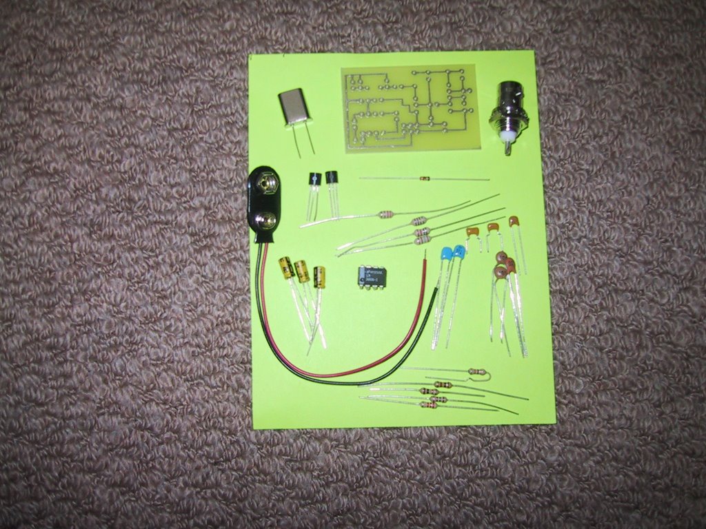
I opened the kit package. Here is the parts that I got.
Crsytal
Board
BNC Connector
Two 2N3904 transistors
Diode
Battery plug
Inductors
Capacitors
LM386
Registors
2N3904 is a power(Pd) with 625mW. I'll replace them with PN2222A. Other source recommends 2N2222A for a better power. If I can get it, I'll use it for pixie2.
MPS2222A is another choice for pixie2 transistors.
I have several 2N4401 and 2SC1815 transistors and would like to try them for pixie2, too.
Pixie2 photos by JE2CDC page
Here is another pixie-2 . It may be made by Kenneke Communications. They are selling Pixie II CW Tranceiver .
Wednesday, October 25, 2006
Got the pixie2 kit

I got the pixie 2 kit today and opened the package. The picture shows the kit, battery connector and crystal. It's very small board and should be easy to build it.
LM386 to get 74dB (Pixie 2 audio amp.)
JF1OZL describes the LM386's circuit with a higher gain. The LM386 gets 40dB as an original circuit provided by the data sheet (10uF pin1-8 connection). This article describes 74dB gain with the circuit.
If you didn't get enough audio gain on pixie 2, you may change to the circuit to get the higher gain.
If you didn't get enough audio gain on pixie 2, you may change to the circuit to get the higher gain.
Tuesday, October 24, 2006
eHam.net review for pixie 2
eHam.net has the review pages for pixie 2. There are 26 reviews about pixie 2 and the average is 3.2/5 which means that it's not good. You should read those reviews before you construct pixie 2 kit.
HSC Electronic Supply
HSC Electornic Supply sells pixie2-KIT as $9.95. This is a good offer to those who would like to have the pixie-2 as a kit. You may build it by yourself because it's easy to construct on the board.
Monday, October 23, 2006
Pixie 2 by M0DAD
M0DAD writes the article of Pixie 2. He mentions that the T1 transistor should be swapped with the better gain of it (e. g. 2N2222) instead of 2N3904.
Monday, October 16, 2006
Zero Beat operation by K3NG
K3NG wrote a good article about An 80 Meter CW Five Watt QRP Tranceivert. In the article, there is the section about the opeartion:
Operation
As this rig has a direct conversion receiver, signals can be heard on both sides of zero beat. In other words, when tuning up the band, you will hear a signal with a high frequency beat note, decreasing as you tune up. The beat frequency continues to get lower until reaching zero beat (dead on the transmit frequency of the other station). Tune further up, and the beat reappears as a low frequency and increases frequency as you continue to tune upwards. This characteristic of direct conversion receivers require a little more thought when tuning on stations and attempting a QSO. Since the transmitter frequency is negatively offset (TX frequency is 600-700 Hz below the RX frequency), one needs to tune on the “high side” of zero beat in order to have the transmit frequency fall within the other station's receiver pass band.
This is a good description of zero beat on the direct receiver.
The article of "Listen to AMATEUR RADIO Signals!" also describes the zero beat by direct conversion on the receiver.
Sunday, October 15, 2006
pixie2 modification on Kenneke Communications
Kenneke Communcations provides the memo for pixie2 modification. It describes the change of Q2 to 2N2222A to increase the output power and the addition of 0.01 uF capacity to ensure RF noise to be bypassed adequately.
It describes the AC BC Band interference to install ferrite chokes. The memo uses 5 mH. It uses 5.62V Zener Diode to be stabalize the power line to LM386. R5 to 500 Ohm and put 250 or 470 uF capacitor from pin 6 on LM386 the GND. It will get immediate improvement audio and bc interference reduction. IT recommends as follows:
It describes the AC BC Band interference to install ferrite chokes. The memo uses 5 mH. It uses 5.62V Zener Diode to be stabalize the power line to LM386. R5 to 500 Ohm and put 250 or 470 uF capacitor from pin 6 on LM386 the GND. It will get immediate improvement audio and bc interference reduction. IT recommends as follows:
- Definately the RF choke going to the audio input of LM386.
- RF Choke on headphone/spkr jack center lead.
- RF Choke to keyed line.
- RF Beads on each line to oscillator/PA resistors.
- Shielding between stages.
Friday, October 13, 2006
RixPix by KE3IJ
The modification of Pixie 2 has been done by Rick Anderson. It calls RixPix. It uses four transistors for audio amplifier instead of LM386 and has the audio filter. The final transistor is 2n3503 to get the higher power than pixie2.
Thursday, October 12, 2006
SPRAT pixie 2 article
SPRAT has the good article of pixie 2. You may refer this article to understand pixie2 and its origin.
Reduce BCI and add sidetone to Pixie2
LA3ZA has the article to reduce BCI and add sidetone to Pixie2. You will use Pin 2 of LM386 to connect diode to the ground instead of pin 6 diode. I will try to use this approach.
The article describe the sidetone of pixie2. Output of sidetone is going to pin 7 of LM386. I'd like to use this sidetone, too.
The article describe the sidetone of pixie2. Output of sidetone is going to pin 7 of LM386. I'd like to use this sidetone, too.
Wednesday, October 11, 2006
G3XBM's pixie2
There is the article of pixie2 written by G3XBM. It describe the pixie2 kit well.
Circuite Swamp has the good explanation page of pixie2. They have the layout of the board. You may refer this page to build pixie2 with the board.
Circuite Swamp has the good explanation page of pixie2. They have the layout of the board. You may refer this page to build pixie2 with the board.
Monday, October 09, 2006
Zero Beat of frequency
Zero beat is always needed to contact other station. AF8X wrote zero beat indicator. It uses LM567 op-amp to indicate the zero beat. The original article was described by WI5W in March 1992 QST magazine.
Another zero beat indicator is called "CW Zero Beat Detector" by Jerry Henshaw, KR5L.
K3WWP shows the zero beat circuit using LM567. It is from a letter sent by W6OWP, he mentioned.
Jackson Harber Press offers the kit of zero beat called "Son of Zerobeat". It has 7 LEDs which graphically inidicate the frequency of a received CW audio tone.
K6XX, Bob Wolbert wrote the visual CW tuning indicator on the Web. It uses XR-2211, FSK/Tone Decoder. LED illuminates as you get within about 25Hz of a signal. It will flash on and off a bit with the incoming signal.
Dixie Pixie2 (Modified pixie2)
The page of modified pixie2 exists. It calls dixie pixie2. VXO and reducing key chattering has been equipted.
Sunday, October 08, 2006
pixie2 article by JJ1SLW
JJ1SLW describes the good article about pixie2. He contacted JA stations from Californica with pixie2, too.
Saturday, October 07, 2006
pixie2 mod by JA9MAT
JA9MAT shows the web page of modified pixie2. He added VXO, AF LPF, sidetone and RIT. It's useful to make the enhanced pixie2.
Friday, October 06, 2006
Press-n-Peel
Press-n-Peel is an interesting technology to make a printed circuit. I'd like to use it sometime future.
Kenneke Communications
There is the memo of pixie2 on Kenneke Communications site. It's useful for me.
Wednesday, October 04, 2006
Pixie2 tips by WE6W
WE6W has a nice tips for pixie2. The RIT should be always equippted with the rig. Audio improvement can be applied to my pixie2. If you can put Zener diode in parallel, it's also stable to operate it.
Anyway, it's considerable to build pixie2.
Anyway, it's considerable to build pixie2.
Monday, October 02, 2006
VXO for Pixie2
The original pixie2 doesn't have the mechanism of variable frequency. The crystal oscillates only one frequency on both sending and receiving time. Typical operation of CW needs to support the CW band for 40m.
VXO (Variable Xrystal Oscillator) is a good option to support the variable frequency for the CW band. The super VXO has two X-tals in parallel and gets the wider range of frequency change with a variable capacitor like trimmer. My first design of frequency converage is 7000KHz-7030KHz, therefore, two 7030KHz X-tals will be used. Inductor and capacitor parameters will be decided to cover the frequency range.
VXO (Variable Xrystal Oscillator) is a good option to support the variable frequency for the CW band. The super VXO has two X-tals in parallel and gets the wider range of frequency change with a variable capacitor like trimmer. My first design of frequency converage is 7000KHz-7030KHz, therefore, two 7030KHz X-tals will be used. Inductor and capacitor parameters will be decided to cover the frequency range.
Wednesday, September 27, 2006
Pixie2 sections
Q1(2N3904) is oscillator using XTAL that connecting to Q2 with C3(82pF). Q2 is mixer between the frequency Q1 and input from antenna. There is the bandpass filter between antenna and Q2 collector. The bandpass filter is C5/C7 (820pF) and L3 (22 uF). Frquency is 1/(2*pi SQRT(LC)) that is7.445 MHz. There is the capacitance C5 (0.01uF) between antenna and Q2 collector to cut the DC effect between Q2 collector and antenna.
Mixer output appears at the Q2 emitter. It's connected to LM386 through C8 (0.1uF). This is the direct conversion receiver, therefore, LM386 should amplify audio freqency with the voltage gain(46dB). D1(1N914) is a diode to prevent current follow to pin 6 on LM386. For pin6 on LM386, DC at +9V DC is supplied through R1 1KOhm. C10 10uF is the purpose to be stabilized at +9V DC. There is 4-7V DC which depends on the current amount to pin 6 on LM386.
C4 is the simple low pass filter beyond the audio frequency. R4 keeps the DC voltage for the Q2 emittor.
Sunday, September 24, 2006
Pixie2 schemantic
I've found the pixie2 schemantics on the we6w's homepage. It is very simple. There are two transistors of 2N3904 and one IC of LM386. Although it's simple, it's a transceiver with a full break-in function.
Power supply is +9V DC and you can use 006P 9V battery for this supply. Crystal in the original schemantic has been equipted, therefore the frequency is fixed for transmitter and receiver. You need to have the RIT for the compatibility of other stations frequency. In addition, the following items are needed:
Power supply is +9V DC and you can use 006P 9V battery for this supply. Crystal in the original schemantic has been equipted, therefore the frequency is fixed for transmitter and receiver. You need to have the RIT for the compatibility of other stations frequency. In addition, the following items are needed:
- VXO to coverage on the range of CW frequency
- Sidetone to hear the CW sending tone
I am investigating to need other additional items for the opeartion. It's the schemantic on May, 1995 and becomes difficult to get information.
Friday, September 22, 2006
pixie2 is started
I am trying to get information on pixie2 for building QRP transceiver. Product review by eham is vary. Some people is rated at 5 but some people is very lower rate.
The kit is sold by HSC Electronic supply at $9.95, but I would like to make it by myself from the parts.
The kit is sold by HSC Electronic supply at $9.95, but I would like to make it by myself from the parts.
Subscribe to:
Posts (Atom)